EE31 Junior Design Project: Self-Navigating Robotic Vehicle
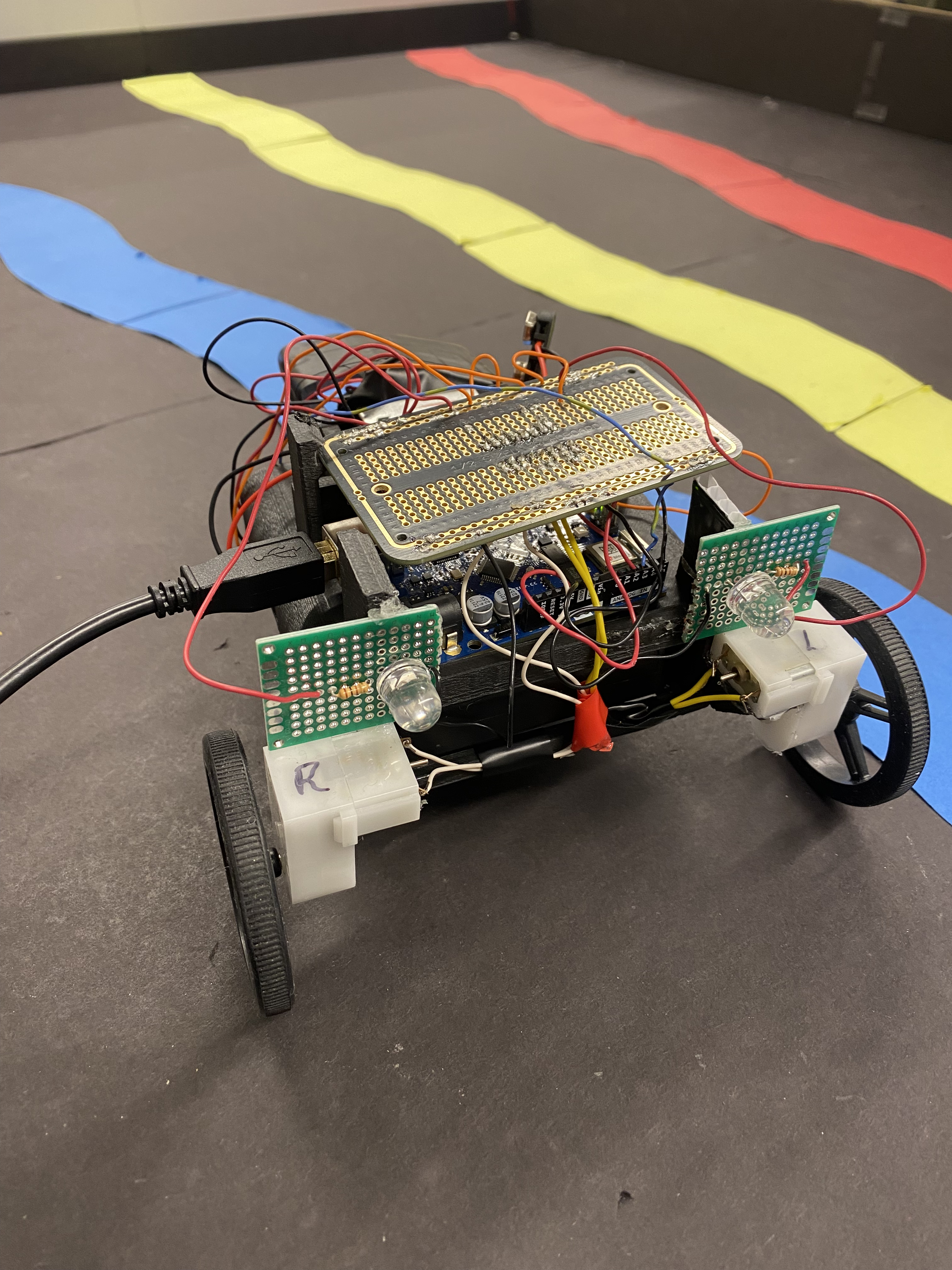


Pictures of the Final Bot Implementation
Project Overview
This project involved designing and building a robotic vehicle capable of self-navigating a test track by following colored lanes and avoiding wall collisions using an Arduino UNO microcontroller. The bot utilized an H-Bridge for motor control, a collision detection circuit with infrared sensors, and a color sensing system to differentiate between track lanes. It was tested in two configurations, following different lane patterns as Bot A and Bot B, with seamless adaptability. A 3D-printed chassis ensured clean wiring and efficient component placement, enhancing performance and durability. The implementation of a WebSocket client allowed real-time communication with a central server, enabling synchronized behavior during team demos. As an additional feature, custom tail lights provided visual feedback during reverse and turning states. This project combined hardware design, sensor technology, real-time communication, and creative features to build a robotic vehicle that’s both functional and reliable.
Introduction
My group consisted of me, Aoife O’Reilly, and Jake Merritt.
For this project, we were tasked with creating a small robotic vehicle or “bot” that can self-navigate on a test track by sensing and following colored lanes. It can also avoid wall collisions by utilizing a wall detection circuit placed at the front of the bot. The bot communicates with other vehicles by making use of a WebSocket client, allowing for two teams to simultaneously traverse the track.
There are two options in which the bot is tested, one as Bot A and the other as Bot B. Both paths are identical, except that Bot A follows the red and yellow lane, while Both B follows the blue and yellow lane and starts on the other side of the course. Bot A’s path can be seen, pictured in Figure 1. Our bot is capable of following both paths while in the course.

Figure 1: Picture Showing Path of Bot A
Circuitry and Functionality

Figure 2: Circuit Schematic and Wiring Diagram
Figure 2 shows the circuit schematic and wiring diagram used to create the bot. In order for the bot to function properly, many different components were needed. Each component was created separately before being wired to the full circuit. An Arduino Uno Rev3 was the microcontroller board used to receive input and control all parts.
H-Bridge Component: An H-Bridge is a circuit used to control the direction and speed of DC motors. It allows the motor to spin forward or backward by reversing the polarity of the voltage applied to it. In this project, the H-Bridge was crucial for enabling the bot to navigate the track, as it allowed precise control of the motors to adjust direction and speed. The H-Bridge was connected to Arduino pins, allowing for control of each motor.
Collision Detection: The collision detection circuit was placed at the front of the bot in order to detect walls, allowing the bot to avoid wall collisions. The circuit used an IR LED to emit infrared light and a phototransistor to detect the reflected light. When the bot approached a wall, the infrared light from the LED would bounce off the wall and be detected by the phototransistor. The closer the bot got to the wall, the stronger the reflected light signals.
Color Sensing: The color sensing circuit worked by shining light from the red and blue LEDs onto the surface below the bot, one at a time, and using the photocell to measure the amount of light reflected back. Different colors reflect red and blue light differently—e.g., red surfaces reflect more red light than blue, while blue surfaces reflect more blue light. By comparing the reflected light intensity from each LED, the circuit could determine the color of the surface the bot was on (black, blue, yellow, or red).
Go Beyond (Tail Lights): As a “Go Beyond” for this project, we added tail lights. Just like the functionality of tail lights in a normal car, both LEDs would light up if the bot was in reverse, and one LED (depending on turn direction) would light up when in a turning state.
3D Printed Chassis


Figure 3: CAD Models
We designed and 3D-printed a custom chassis for the bot to prioritize clean wiring and efficient component placement. The chassis included designated compartments for the batteries, Arduino board, motors, and additional circuits, simplifying troubleshooting and minimizing the risk of wire tangling or component damage.
By stacking the 5V battery pack, Arduino, and main protoboard, we optimized the use of space, resulting in a compact and efficient design. This layout not only enhanced the bot’s visual appeal but also improved its performance during testing, as it rarely collided with walls unless the collision detection system failed. Figure 3 shows three views of the CAD model illustrating the final design.
The WebSocket implementation enabled real-time communication between the bot and a central server, playing a crucial role in both solo and team demos. During team demonstrations, where two bots operated simultaneously, the WebSocket facilitated seamless communication between the bots, ensuring synchronized behavior and preventing collisions. Commands were sent through the WebSocket to initiate specific actions, such as starting or stopping the bot, allowing for precise control during demos.
WebSocket
Video Demos
Video Demonstrating Solo Track Navigation as Bot B
Video Demonstrating Joint Track Navigation as Bot A